
Automating Register Verification with 100% Functional Coverage
By Louie de Luna, Agnisys Director of Sales and Marketing
UVM has certainly improved the reusability of verification environments for SoC projects, significantly lowering the verification costs throughout the electronics industry. Since Accellera’s release in 2011, UVM is now an IEEE standard published as IEEE 1800.2-2017 – IEEE Standard for Universal Verification Methodology Language Reference Manual. UVM has definitely gone a long way.
The UVM Register Layer classes have been quite useful for modeling memory-mapped registers and external memories in a DUT in which users are able to abstract the verification environment and standard tests from block to system level seamlessly with only minimum modifications. However, today’s average electronics consumer demands new use cases at ever-increasing speed and bandwidth – which certainly challenges SoC architects, designers, and verification engineers, requiring them to be more creative in the implementation and modeling of the hardware/software interface (HSI). In order to fulfill special register behavior, which includes well-known types such as Shadow, Alias, Lock, trigger buffer, and Counter (just to name a few), it is necessary to model special registers. Creating the RTL for these special registers may be easy to do for some experts but modeling them in UVM and manually creating the test environment with 100% functional coverage can be daunting.
Register Verification Challenges
Although full-blown in-house scripts are available in large international SoC companies capable of generating RTL, UVM register model, and a working UVM verification environment, most lack in several key areas for verification and do not provide 100% functional coverage. On average the standard UVM sequences provided as part of the UVM give less than 50% functional coverage out of the box. The in-house scripts still need to address the following verification challenges:
- There are interface points between the generated and the manually created RTL that need to be verified. For example, the interface between the hand-crafted code (“external” register, memory instance, IP logic) and the auto-generated register code must also be verified.
- The verification environment should include software-side agents and hardware-side agents. The hardware side agents are not fixed; their dependency lies on the specification. If an engineer changes the hardware access for a bit field from read-only to read-writeable, it necessitates a modification to the hardware side agent.
- The generated register models need to be integrated into the verification environment. The generated model must have the structural information about the registers, bit fields, their access, and addresses. Additionally, it should be comprehensive, and should also have cover groups and cover points with illegal bins, otherwise the quality and completeness of the tests cannot be meaningfully ascertained.
- Create transactions for both software and hardware logic. Write tests to assess a range of special functionalities linked to the registers.
- Running all these tests generates a lot of simulation data thus a dynamic test plan is needed. We say “dynamic” because a change in the specification needs to be reflected in the plan. For example, a new field added, or access changed may need additional tests. Such a test plan must be auto-updated once all the tests have been run, otherwise the project risks missing critical tests that could cause a bug to make its way into the chip.
How to Automate a Complete Register Verification Environment
The good news is that all this can be automated to a great extent so that verification teams do not have to spend time manually developing the required verification environment, tests, and test plan. The automatic register verification solution should employ the components and setup depicted in Figure 1.
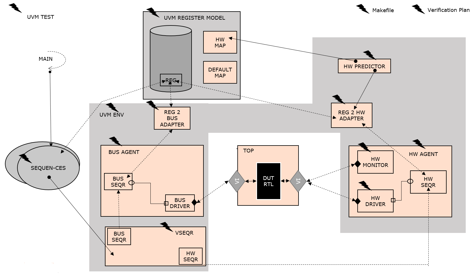
Mainly, you should be able to dynamically take in Address Map specification in the form of Word/Excel/FrameMaker or textual standards like SystemRDL, IP-XACT, or RALF. From the specification, you can auto-generate the following for a simulation-based environment:
- Generate the RTL (SystemVerilog/SystemC) and generate the UVM Reference model (SystemVerilog/SystemC)
- Take in additional information such as the register buses used for the address map, the least addressable unit, hdl_paths of each register, register group, memory, or block.
- Generate agents for the register buses. These agents must include the corresponding drivers and monitors. Generate hardware side agents including the hardware side driver and monitor. The hardware-side driver simulates transactions sent to the address map by the application logic. The hardware monitor captures the same transactions used for updating the UVM Regmodel with correct values.
- Generate a hardware side predictor that gets these transactions from the hardware monitor and predicts the correct value in the UVM model according to the access policies of the Register fields.
- Generate a UVM environment class that contains all the above components.
- Generate sequences for each and every register according to their software access and additional special behaviors.
- Generate a UVM Test class to run all the above sequences.
- Generate a top-level module connecting the generated RTL module and bus interfaces.
- Generate a “Makefile” to run the simulations and collect results from the simulation database appropriate for the simulator being used.
- Generate a verification plan with the ability to back-annotate these simulation results so that engineers can analyze the results.
If you’d like to see working examples of this automation and the generated results, feel free to contact us.
I invite you to view our recorded webinar, 5 Special Registers Useful for Today’s SoCs – Use Cases, Examples and UVM Verification Best Practices, where we introduce 5 special registers that are widely adopted in the industry. We provide their benefits, use cases, and examples (RTL, UVM model, and C-Header Files). We also provide best practices on how to verify them where you can achieve 100% functional coverage. In addition, we touch upon a subject that’s very important for large SoC developers, and that is the performance of the register layer.


