
Three Steps to Set Up a RISC-V SoC UVM Testbench
Verifying any large chip design is challenging, but a system-on-chip (SoC) presents additional requirements. By definition, an SoC includes one or more embedded processors, and the code they execute provides a significant portion of the overall functionality. While lint checks, formal analysis, and other techniques play a role, the majority of verification involves simulating a testbench compliant with the Universal Verification Methodology (UVM) standard to ensure that both hardware and software are verified together (co-verified) for exercising the full range of intended operation.
Such a testbench environment is a must-have requirement for every SoC project. It provides a means to check the full system before sending the design to the foundry for fabrication. It complements block-level testbenches by verifying that all the connections between the blocks are functioning correctly, that data flows properly around the SoC, and that hardware interrupts and their associated interrupt service routine (ISR) software are working. The testbench can also help the firmware and software engineers write and debug device drivers and applications. Setting up the SoC verification environment can be divided into three steps:
- Creating a testbench compliant with the UVM architecture
- Converting C programs to binary files for the embedded processor(s)
- Synchronizing C programs and UVM tests
The process is similar for any type of embedded processor, but this post focuses on RISC-V since it is a widely used instruction set architecture (ISA) for contemporary SoCs.
There are many excellent readily available classes and references on setting up a UVM-compliant testbench. Benefits of this approach include:
- The ability to write directed and random tests to verify the various aspects of the SoC
- A raise/drop objection mechanism to provide the flexibility to control the tests
- Use of powerful SystemVerilog features such as assertions and functional coverage
Reuse of UVM agents written for interface IP blocks on pins of the SoC
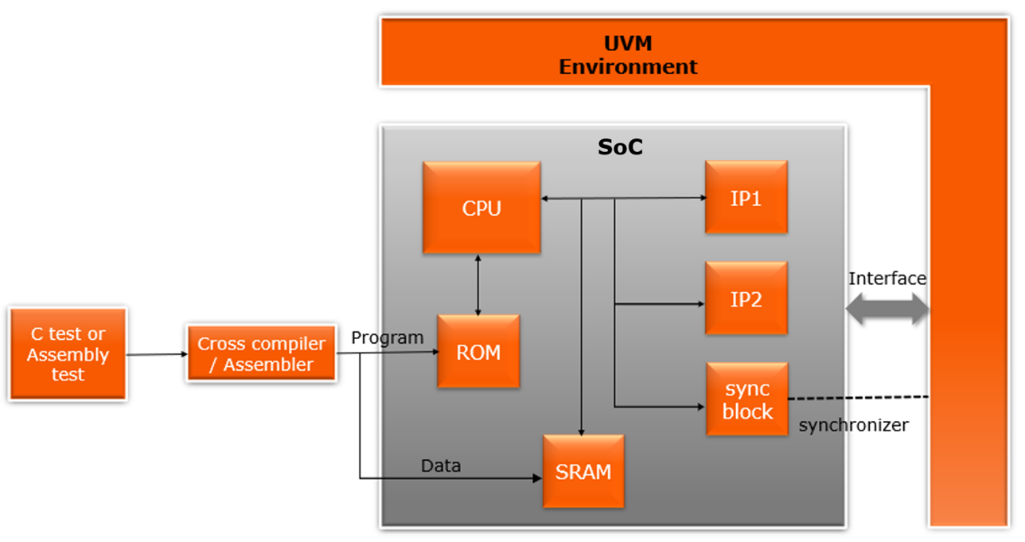
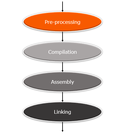
If a design does not contain any processors, the UVM test bench is sufficient for verification. For a RISC-V SoC, you need to pair the UVM tests with C tests that run on the embedded processor. In the second step, compile, assemble, link, and load these tests into the design’s memory to enable them to co-simulate with the UVM testbench. For RISC-V, there is an industry-standard toolchain available to support this flow. The first stage is running a standard C pre-processor to remove comments, expand macros and included files, and handle conditional compilation options. In the compilation stage, the preprocessed code is translated into assembly instructions specific to the target processor architecture. The RISC-V assembly instructions are converted to object code, the actual instructions to be run by the embedded processor. Finally, the linker arranges the sections of object code so that functions in some sections can successfully call functions in other ones. It also adds sections containing the instructions for library functions called by the program.
The RISC-V toolchain provides a command to compile, assemble, and link C code for its ISA. For example, the following command creates a test for a GPIO block:
riscv32-unknown-elf-gcc ../start.S ../test.h ../gpio.h ../gpio.c -o gpio.o -static -nostdlib -nostartfiles -lm -lgcc -T ../link.ld
The test.h and gpio.h files contain the register information of the test block and GPIO block in the form of C structures. These structures are used for reading and writing to the block registers, and they are automatically generated with the help of IDesignSpec™ from Agnisys. gpio.c contains the code for initializing and testing the GPIO block, and link.ld is a custom linker script that tells the linker in which memory locations to put different sections of the code. Finally, the start.S file contains assembly instructions for startup code run prior to the programs, including initialization of registers and the stack pointer.
The Verilog functions $readmemh and $readmemb are used to load the object code into instruction memory and to load data into data memory within the SoC simulation model. At this point, the UVM testbench and the embedded code can be run together. However, to verify the design properly each UVM test must be synchronized with its corresponding C program. This enables important capabilities, including:
- Driving SoC pins after certain blocks are configured for testing some features
- In the C program, stopping for events that are triggered by the UVM side
- Generating errors for testing purpose from the C program
- Finishing the UVM test when the C program has completed its execution
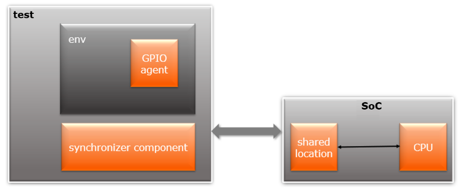
For synchronization, we use dedicated locations in the SoC memory or registers within the target block to facilitate the sharing of information between C programs and UVM tests. C programs access this shared space by bus access (front door) and the UVM testbench can access it directly (back door). This method supports handshakes between C and UVM as well as data transfer.
More information on this approach, including details of interrupt verification and synchronization registers, is available in a webinar, part of an extensive series covering a broad range of design and verification topics. DV engineers can register here at their convenience to learn how to verify RISC-V SoCs with a sophisticated and powerful UVM-based testbench with support for embedded programs.


