
Chip-in-Chip support for multiple input format
Introduction
IDesignSpecTM supports multiple design hierarchies like “chip”, and “block” to enable different architectural design flows. A block can contain registers. A chip can contain other blocks and provide an aggregator for the blocks.
A large SoC Design often requires multiple levels of hierarchies to place or group different block IPs, so that these block hierarchies can be placed at different offsets in an address map or can even be on different address maps from both design and verification points of view. Chip-in-Chip hierarchy provides functionality to aggregate the different block IPs and address decoding at every level of the hierarchy.
To remove the limitation on the number of hierarchies over block level, chip-inside-chip is supported with input IDS-Word, IDS-Excel, IDS-NG, SystemRDL, and IDS-Calc.
Now a chip can be a container for other chip hierarchies in addition to block hierarchies.
Use Cases
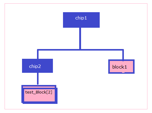
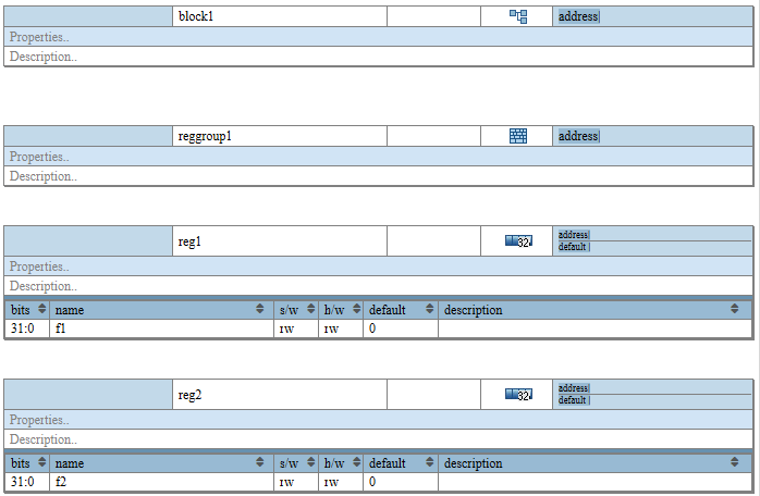
Below diagram showing the chip-in-chip hierarchy:
- Chip1 contains two elements “chip2”(chip element) and a “block1”(block Element).
- Chip2 contains “test_Block”(block element) with a repeat of two.
The property: “chip=true”
Chip-Inside-Chip flow is supported using the property “chip=true”. For example, in the case of a top chip, in IDS-Word specification having multiple chip(container) hierarchies, chips having the property “chip=true” would be considered chips.
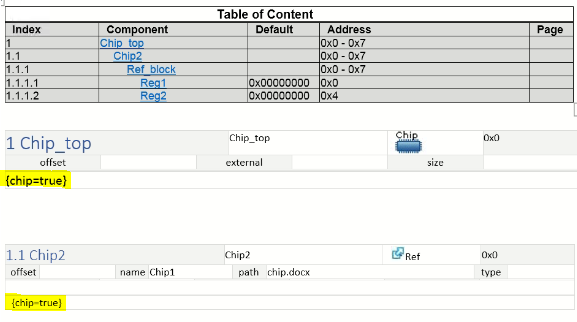
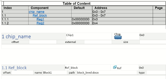
IDSWord Example
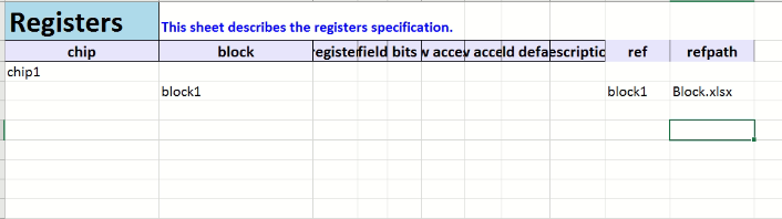
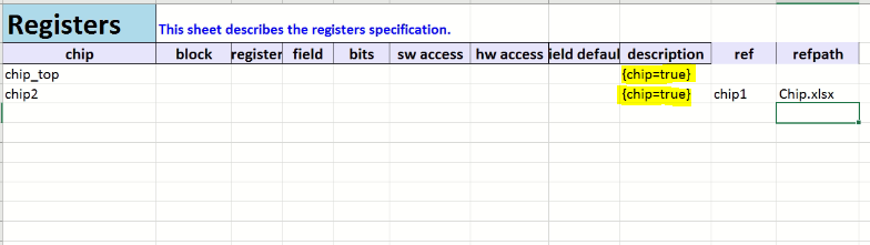
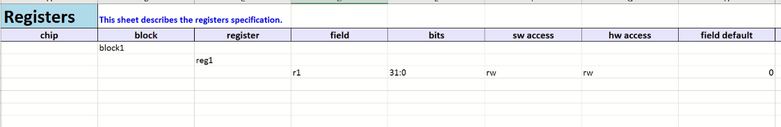
IDS-Excel Example
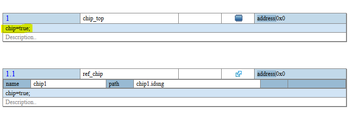
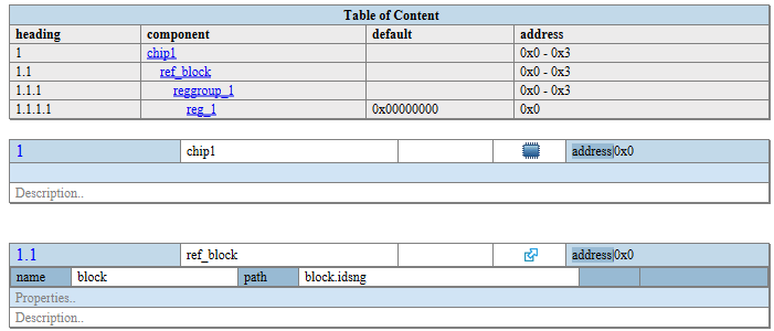
IDS-NG Example
SystemRDL Example
property chip { type = boolean; component = addrmap; };

addrmap Chip2 {

   chip=true;

   addrmap Chip1 {

     chip=true;

      addrmap Block1 {

       reg reg1 {

         field {

         sw=rw;

         hw=rw;

         }f1[31:0]=0;

       };

      reg1 reg1;

      };

      addrmap Block{

        reg reg2 {

         field {

         sw=rw;

         hw=rw;

         }f1[31:0]=0;

       };

       reg2 reg2;

      };

   Block1 Block1;

   Block2 Block2;

  };

  addrmap Block3 {

       reg reg3 {

         field {

         sw=rw;

         hw=rw;

         }f1[31:0]=0;

       };

       reg3 reg3;

      };

 Chip1 Chip1;

 Block3 Block3;

 };
Conclusion
- IDesignSpecTM supports chip-in-chip hierarchies, which means users can add chip inside chip along with block by using any IDS format like:- IDS-NG, IDS-Word, IDS-Excel, SystemRDL, IP-XACT, etc.
- For SystemRDL, users can use addrmap and apply the “chip=true” property for each addrmap, on which they want to make a chip.
- For other IDS input formats, users need to use the reference of the child chip as the ref template and apply the “chip=true” property on that template. The referred file can be any IDS input format. Also, this feature is supported for IDS output like:- RTL, UVM, Header, and Documentation(HTML, PDF).


