Automating the UVM Register Abstraction Layer (RAL)
The Universal Verification Methodology (UVM) has become a standard for verifying complex digital designs. One of the key components of UVM is the Register Abstraction Layer (RAL), which provides a standardized way to model and access hardware registers in a design. However, creating and maintaining RAL models manually can be a tedious and error-prone process. This is where automation tools like IDesignSpec(IDS) can streamline the development process.
IDS is a tool developed by Agnisys that takes input specifications of registers and automatically generates UVM RAL models. This automation not only reduces the time and effort required to create RAL models but also helps ensure consistency and correctness across different parts of a design.
Benefits of Using IDS
- Time Savings: Automating the generation of RAL models with IDS can save a significant amount of time compared to manual creation.
- Consistency: IDS ensures that all RAL models are generated following the same rules and conventions, leading to more consistent designs.
- Error Reduction: By automating the generation process, IDS helps reduce the chances of errors in RAL models, improving overall verification quality.
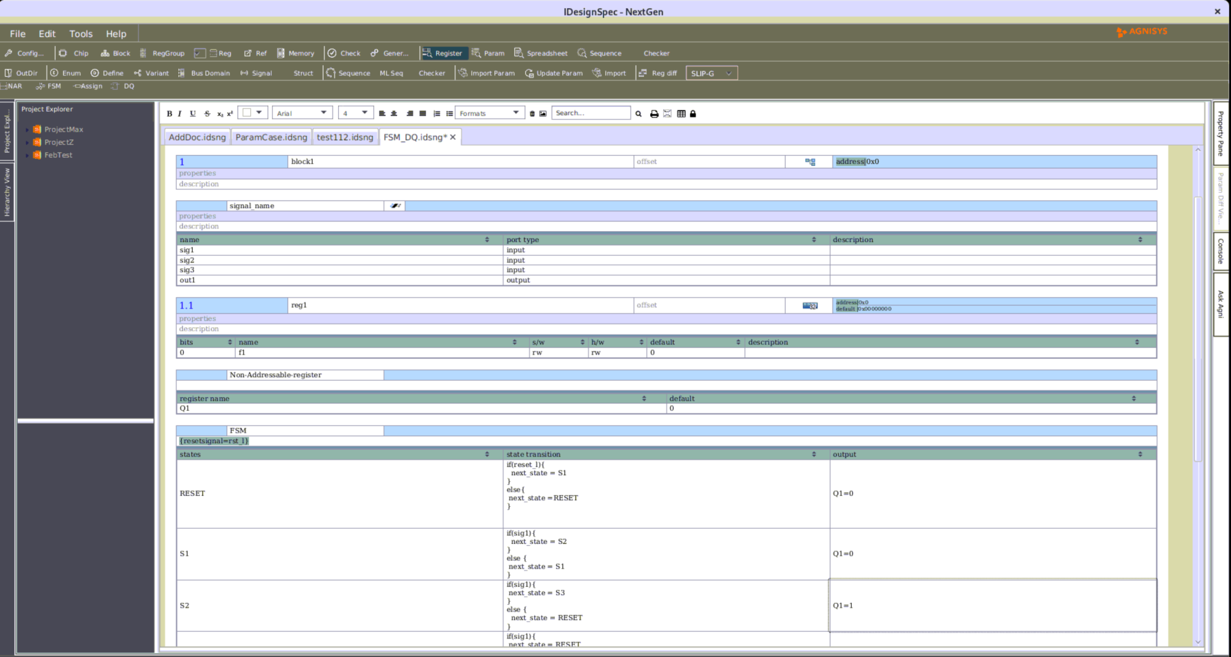
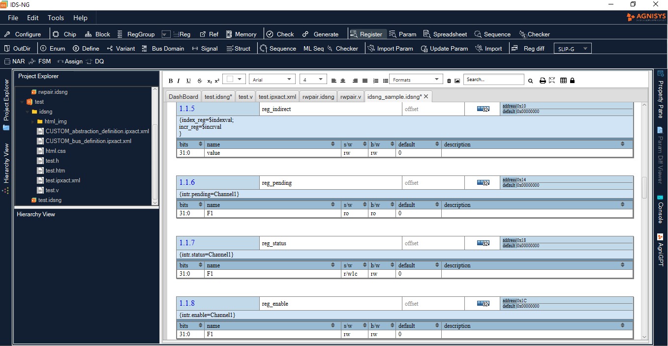
- Ease of Use: The tool’s user-friendly interface makes it easy for designers to input register specifications and generate RAL models without needing deep knowledge of UVM internals.
How IDS Works
IDS takes input specifications in IDS supported input formats(SystemRDL, IP-XACT, IDS-NG, IDS-Word, IDS-Excel, PSS, Agnisys XML, Custom XML, YAML, JSON, CSV, RALF) and uses this information to generate UVM RAL models. The input specifications include details such as register addresses, bitfields, access policies, and reset values.

The tool parses the input specifications and generates UVM classes for each register in the design. These classes include methods for reading and writing register values, as well as accessing individual bitfields.
Case Study: Applying IDS in a Complex SoC Design
To illustrate the effectiveness of IDS, let’s consider a case study where IDS was used to automate the generation of RAL models for a complex System-on-Chip (SoC) design.
In this scenario, the SoC contains multiple IP blocks, each with its set of registers. Manually creating RAL models for these registers would be a time-consuming and error-prone task. However, by using IDS, the design team was able to quickly generate RAL models for all IP blocks, saving weeks of effort.
Furthermore, as the design evolved, the team could easily update the input specifications and regenerate the RAL models, ensuring that the verification environment remained up-to-date with the latest design changes.
Here is the example of how to user can generate UVM RAL from RDL spec :-
Input RDL Spec : –
This spec has been created using the specialized RDL editor for VS Code. More details can be found here:- https://marketplace.visualstudio.com/items?itemName=AgnisysInc.agnisysrdl-beta
addrmap gpio {
    reg LED_control {
        regwidth = 8;
        field {
            hw = na;
            sw = rw;
        } LED0_value[0:0]=0;// LED0 enable/disable, 0-disable, 1-enable
        field {
            hw = na;
            sw = rw;
        } LED1_value[1:1]=0;// LED1 enable/disable, 0-disable, 1- enable
        field {
        hw = na;
        sw = rw;
        } LED0_Func[2:2]=0; // LED0 as i/p or o/p, 0-output, 1-input
        field {
        hw = na;
        sw = rw;
        } LED1_func[3:3]=0;// LED1 as i/p or o/p, 0 for output, 1- input
        field {
        hw = na;
        sw = rw;
        } F5[7:4]=0;
    };
   reg LED0_reg {
        regwidth = 8;
        field {
            hw = na;
            sw = rw;
        } LED0[0:0]=0; // to on/off led0 , 0 to off, 1 to on
        field {
            hw = na;
            sw = rw;
        } F2[1:1]=0;
        field {
            hw = na;
            sw = rw;
        } F3[2:2]=0;
        field {
            hw = na;
            sw = rw;
        } F4[3:3]=0;
        field {
            hw = na;
            sw = rw;
        } F5[7:4]=0;
   };
   reg LED1_reg {
        regwidth = 8;
        field {
            hw = na;
            sw = rw;
        } LED1[0:0]=0; // to on/off led1 , 0 to off, 1 to on
        field {
            hw = na;
            sw = rw;
        } F2[1:1]=0;
        field {
            hw = na;
            sw = rw;
        } F3[2:2]=0;
        field {
            hw = na;
            sw = rw;
        } F4[3:3]=0;
        field {
            hw = na;
            sw = rw;
        } F5[7:4]=0;
   };
   LED_control LED_control;
   LED0_reg LED0_reg;
   LED1_reg LED1_reg;
};
Command line to generate UVM RAL :-
idsbatch “gpio.rdl” -out “uvm” -dir <output_dir>
Generated UVM RAL :-
/*----------------------------------------------------------------------
Class       : gpio_LED_control
DESCRIPTION:-
-----------------------------------------------------------------------*/
`ifndef CLASS_gpio_LED_control
`define CLASS_gpio_LED_control
class gpio_LED_control extends uvm_reg;
    `uvm_object_utils(gpio_LED_control)

    rand uvm_reg_field LED0_value;/**/
    rand uvm_reg_field LED1_value;/**/
    rand uvm_reg_field LED0_Func;/**/
    rand uvm_reg_field LED1_func;/**/
    rand uvm_reg_field F5;/**/

    // Function : new
    function new(string name = "gpio_LED_control");
        super.new(name, 8, build_coverage(UVM_NO_COVERAGE));
        add_coverage(build_coverage(UVM_NO_COVERAGE));
    endfunction
 // Function : build

    virtual function void build();

        this.LED0_value = uvm_reg_field::type_id::create("LED0_value");

        this.LED0_value.configure(.parent(this), .size(1), .lsb_pos(0), .access("RW"), .volatile(0), .reset(1'd0), .has_reset(1), .is_rand(1), .individually_accessible(0));

        this.LED1_value = uvm_reg_field::type_id::create("LED1_value");

        this.LED1_value.configure(.parent(this), .size(1), .lsb_pos(1), .access("RW"), .volatile(0), .reset(1'd0), .has_reset(1), .is_rand(1), .individually_accessible(0));

        this.LED0_Func = uvm_reg_field::type_id::create("LED0_Func");

        this.LED0_Func.configure(.parent(this), .size(1), .lsb_pos(2), .access("RW"), .volatile(0), .reset(1'd0), .has_reset(1), .is_rand(1), .individually_accessible(0));

        this.LED1_func = uvm_reg_field::type_id::create("LED1_func");

        this.LED1_func.configure(.parent(this), .size(1), .lsb_pos(3), .access("RW"), .volatile(0), .reset(1'd0), .has_reset(1), .is_rand(1), .individually_accessible(0));

        this.F5 = uvm_reg_field::type_id::create("F5");

        this.F5.configure(.parent(this), .size(4), .lsb_pos(4), .access("RW"), .volatile(0), .reset(4'd0), .has_reset(1), .is_rand(1), .individually_accessible(0));

    endfunction

endclass

`endif

…

…

…
- Alias
- Lock
- Counter
- Interrupts
- TMR
- Virtual register
Conclusion
Automating the UVM Register Abstraction Layer with IDS can significantly improve the efficiency and quality of the verification process for digital designs. By automating the generation of RAL models, designers can save time, reduce errors, and ensure consistency across their designs. IDS’s user-friendly interface makes it easy for designers to integrate automated RAL generation into their verification flow, making it a valuable tool for any verification team. IDS can handle complex (quirky or special) registers which helps reduce the workload on the verification team allowing them to focus on other parts of the IP/SoC functionality.


