

In my previous blog post, I shared a few case studies of how our customers deploy our tools and why they love the benefits we provide on their chip and IP projects. I asked our Applications Engineering team to investigate further and document some of the design and verification flows in which our tools are used. They put together a few very nice flow diagrams, so I think that it will be interesting to share them. It may give you some new ideas about how we can help with your current and upcoming projects.
CI/CD of Register Data
Many of our users rely on a methodology of continuous integration and continuous deployment (CI/CD). Designs and testbenches evolve many times over the course of a project, and it is valuable to incorporate the changes quickly and reflect them in all activities. Our specification automation approach is unparalleled for enabling the CI/CD approach. Since we generate many design, verification, software, validation, and documentation files automatically, updating the source specifications triggers re-generation, keeping all files and activities up to date and in sync.
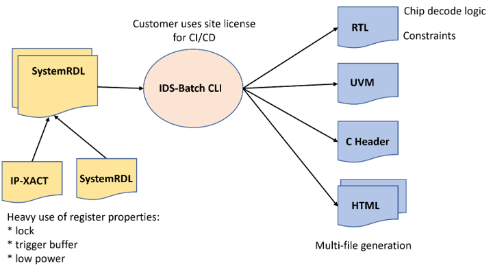
Whenever any change in the project affects the registers, the users update the IP-XACT or SystemRDL specifications as appropriate. They use IDS-Batch™ CLI to re-generate a wide array of project files automatically. These files are distributed to the teams as needed: register transfer level (RTL) code to the designers, Universal Verification Methodology (UVM) files to the verification engineers, C headers to the programmers, and HTML documentation to the technical writers. This happens on an ongoing basis throughout the project, enabling a true CI/CD flow.
Common Link to Jama
In addition to traditional design and verification tools, many projects use third-party software for bug tracking, project management, and requirements management. One group of Agnisys users relies on the Jama Connect requirements management platform to centralize all the features of their projects. This list includes the chip registers and details of their contents, including fields and bits. Since their registers are defined in multiple specifications, they need a flow that combines all register information and provides a common link to Jama. Our tools provide this link.
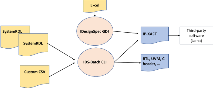
In a manner similar to the first customer I discussed, IDS-Batch CLI reads in multiple SystemRDL files and merges them into a register definition. Some additional registers are defined by custom comma-separated value (CSV) files, which IDS-Batch CLI also handles. In addition, the team has the ability to define registers using Excel spreadsheets, which are read into IDesignSpec™ GDI. There they can be edited using the IDS-NG™ graphical interface. Both of our tools generate IP-XACT files of the resulting registers, which are managed as requirements by Jama.
Large Team Using Registers and Sequences
When we generate UVM files for registers, we automatically provide testbenches and high-coverage tests appropriate for the register types. We support dozens of special registers, including indirect, indexed, read-only/write-only, alias, lock, shadow, interrupt, counter, paged, virtual, external, read/write pairs, and combinations of types. We understand how to access these registers from the tests in UVM testbenches and from drivers/embedded code in the software. If users wish to specify custom access sequences in addition, we provide that capability.
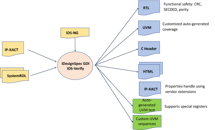
The flow is similar to the previous two cases, with the key addition of custom sequences as required by the users. In addition to register specification and editing, IDS-NG enables the definition of sequences using natural language. It supports loops, conditionals, and all the features you’d expect when defining programming sequences. IDS-Verify™ generates UVM code for the custom sequences in addition to the usual automatic tests. This customer’s designs operate in safety-critical applications, so we also generate RTL safety mechanisms to detect chip failures and correct them when possible.
SoC Pre-Silicon Validation
UVM tests and testbenches verify the RTL register designs, but the registers still need to be accessed by software. This may be from drivers on a host system or from embedded code running on processors within the design itself. Final system on chip (SoC) hardware-software validation occurs in the bring-up lab after chips are back from the foundry, but this is much too late to find design bugs. It is essential to co-simulate the RTL design, the UVM testbench, and the software running together for pre-silicon validation. We fully support this flow.
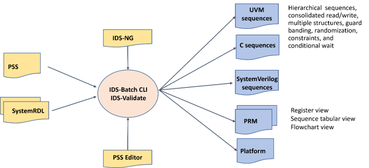
This customer uses IDS-Validate™ to generate not just UVM sequences, but also C sequences that can run in drivers and embedded code. As shown above, these sequences are quite complex. We can also generate pure SystemVerilog sequences for teams not using UVM. Note that this team also uses the Portable Stimulus Standard (PSS), which can define both registers and sequences. We provide a feature-rich PSS editor to help them develop their code. Also note that these users incorporate the documentation we generate directly into their programmer’s reference manual (PRM).
Top-Level SoC Assembly and Packaging
So far I’ve focused on how users set up flows with our tools for design and verification of IP blocks, modules, or subsystems, although typically some verification and pre-silicon validation is performed at the full-chip level. This requires a more or less complete RTL design, which takes a lot of time and effort if built manually. Given the similarities in signal and module names, it is very easy to make mistakes in the chip assembly process. Debugging and fixing these takes even more time and effort. Fortunately, we have a way to automate this part of your project as well.
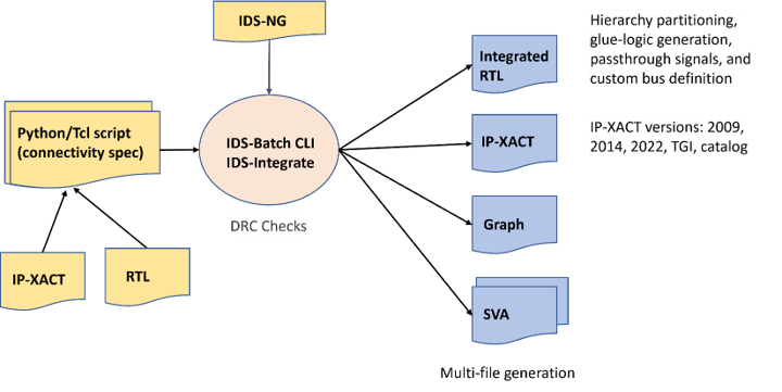
This customer makes use of IDS-Integrate™ to connect all their modules and subsystems into a full top-level SoC RTL design. They specify their desired connectivity with a simple script, and we do all the tedious work of wiring everything together. We generate glue logic such as bus bridges when needed between the modules, supporting both standard and custom buses. The output RTL design is complete and ready for full-chip verification and validation. We also generate a set of SystemVerilog Assertions (SVA) that you can use to check connectivity using simulation or formal methods.
A Final Word
As I mentioned in my last post, I can talk at great length about the many creative ways our customers use our tools. The five flows I’ve selected today are representative, but only a small set of case studies that we could present. If you’d like to hear more, please contact us anytime.
