Automating the UVM Register Abstraction Layer (RAL)
It’s hard to think of any electronic design automation (EDA) innovation that’s had more impact than the Universal Verification Methodology (UVM). After decades of ad hoc designer-centric simulation and a few advanced verification teams using more automated methods, the UVM brought everyone involved in chip development into a new era. Verification engineers have ready access to object-oriented programming, constrained-random stimulus, self-checking tests, reusable models, functional coverage, assertions, and more. Industry standards, UVM, and the SystemVerilog language it’s built on, enable teams to mix EDA tools from various vendors and easily switch tools if desired.
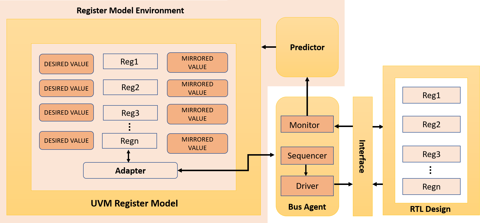
This post focuses on the UVM Register Abstraction Layer (RAL), sometimes called the UVM Register Layer. Today’s large system-on-chip (SoC) designs contain many control and status registers, often accessible from embedded software or drivers as well as hardware. In verification, a crucial early step involves checking the correct functionality of these registers. Subsequently, the design requires manipulation and tracking of the registers during the execution of functional tests. The UVM RAL provides a standardized set of base-class libraries and methods that make it easy to build an object-oriented model to access memory-mapped registers—and memories—in the design. The model includes register components that mirror the values of the registers in the design and hold the expected values of the registers to check test results.
Verification engineers can take advantage of an application programming interface (API) that includes the following methods:
-
- write()/read()
- Execute a physical write/read on the register transfer level (RTL) design
- After a write, the mirrored value is updated
- Execute a physical write/read on the register transfer level (RTL) design
- poke()/peek()
- Write/read directly to the RTL register, bypassing the physical interface
- After a write, the mirrored value is updated
- Write/read directly to the RTL register, bypassing the physical interface
- set()/get()
- Write/read the desired value component directly, without accessing the design
- update()
- If the desired value is different from the mirrored value, invoke the write() method
- Hence the mirrored value is updated
- If the desired value is different from the mirrored value, invoke the write() method
- mirror()
- Invoke the read() method to update the mirrored value to match the RTL design
- May compare the design value with the mirrored value before updating
- Invoke the read() method to update the mirrored value to match the RTL design
- write()/read()
The UVM RAL provides many features to create models that reflect the complex register and memory structures in today’s SoCs.Multiple fields within each register allow independent reading or writing. Register files, grouping multiple registers or sub-files, can contain any number of registers.. Register blocks may contain any number of registers, register files, memories, or sub-blocks. For each element in a register model—field, register, register file, memory, or block—there is a class instance that abstracts the read and write operations on that element. The UVM RAL supports both front-door register access, using the hardware physical interface, and back-door access directly to the RTL register. The UVM RAL also includes a register test sequence library with predefined test cases that can be used to verify the registers and memories.
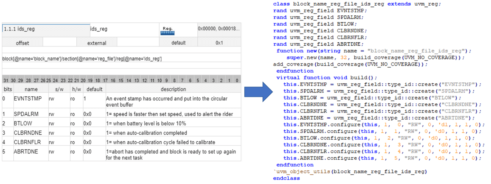
With all this flexibility and power, writing the UVM RAL model is not a trivial task. The standard base classes, methods, and sequences provide a great foundation, but verification teams would like to automate the creation of RAL models as much as possible. Fortunately, it is easy to automatically generate these models and the RTL code at the same time, both from a common specification. The IDesignSpec (IDS) solution from Agnisys provides this capability, supporting numerous specification formats including the SystemRDL standard. For even more automation, verification engineers can use an Agnisys-supplied plug-in to Microsoft Word or Microsoft Excel to specify their registers in an intuitive graphical format. In the figure below, the user is specifying a register with 6 distinct, named bit fields. IDS takes this input and automatically generates the UVM RAL model shown to the right of the arrow.
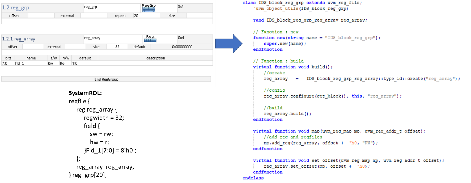
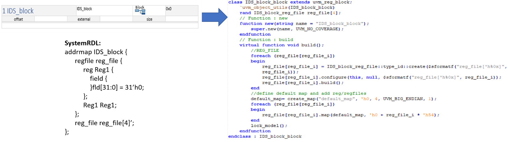
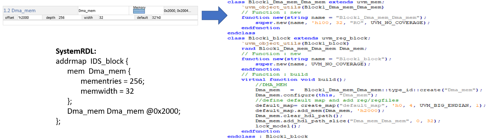
Specifying a register file is equally straightforward, as shown in the following figure. The corresponding SystemRDL description is included. SystemRDL is one of the possible outputs from IDS, but it can also be an input for users who wish to write the description manually rather than use the plug-ins or the dedicated editor included in the Agnisys IDS-NG solution. The definitions for a register block containing multiple register files and for memory are also illustrated.
IDS provides many options to reflect the diverse nature of SoC designs. Register, fields, and bits can be specified as read/write or read-only, with different values possible for hardware and software access. This is especially useful for configuration registers that are set by embedded software at boot time and then read but never changed by the hardware design. IDS supports more than 20 special register types, including shadow, lock, trigger buffer, interrupt, counter, and external. The generated RTL designs and the UVM RAL models reflect these options accurately. IDS can optionally include functional coverage in the generated register models. This includes coverage for the bits read or written, the values in fields, the addresses read or written in an address map, or any combination of these. The user has full control over what type of coverage code is generated for any particular register or block.
The RAL is a good example of the sophisticated verification techniques enabled by the UVM. SoC development teams can define arbitrarily complex registers and memories, secure in the knowledge that they will be able to verify the designs containing these structures. Agnisys IDS elevates register and memory design and verification to the next level by providing easy specification and automatic generation of RTL code, UVM RAL models, C/C++ headers for embedded programmers, and multiple forms of documentation. This capability benefits every member of the SoC team, in particular verification engineers writing and running UVM-based tests. An extensive webinar is available with much more detail well beyond the scope of this post.