
An Update on Functional Safety and ISO 26262
Just about a year ago, I published a blog post about the emerging need for better functional safety and security in a wide range of electronic products. We recently held a webinar on functional safety and how we enable it, and this prompted me to think about the topic again. As I talked to our experts and heard feedback from customers, I realized that it was time to revisit safety. Although the webinar is the best source for the technical details, I’d like to give you a taste of the design and verification automation we provide for chips in safety-critical applications.
In the year since my original post, it is clear that functional safety has become more important not just to engineers, but also to end users. Autonomous vehicles remain a very hot topic, and several recent high-profile accidents have brought safety—of all kinds—to the forefront. It’s hard enough to address the challenges of proper self-driving operation even under ideal conditions. But imagine an alpha particle flipping a memory bit, or an aging component misbehaving, or a cable breaking due to mechanical stress. Functional safety is all about the vehicle responding correctly to such failures, for example by slowing down and pulling off the road.
Designers of automotive electronics and car companies are keenly aware of the ISO 26262 standard for functional safety, and even some consumers are learning about it. We’re not at the point where dealerships advertise ISO 26262 compliance in their showroom windows, but the standard certainly can’t be ignored. It requires that failures in safety-critical logic be detected and either corrected or handled with appropriate responses. Fortunately, designers have readily available a range of techniques to guard against failures, detect them if they do occur, and take appropriate action.
Surely the most widely known method for error detection is adding parity bits to buses, registers, and memories. Adding a parity bit, or check bit, to a string of data bits ensures that the combined result has either an odd or even number of 1s. The concept is straightforward: if a memory bit flips due to a cosmic ray or noise flips a bus bit, the incorrect number of 1s will signal an error, and detection will occur. However, parity does not facilitate error correction, so a response to the error is necessary.
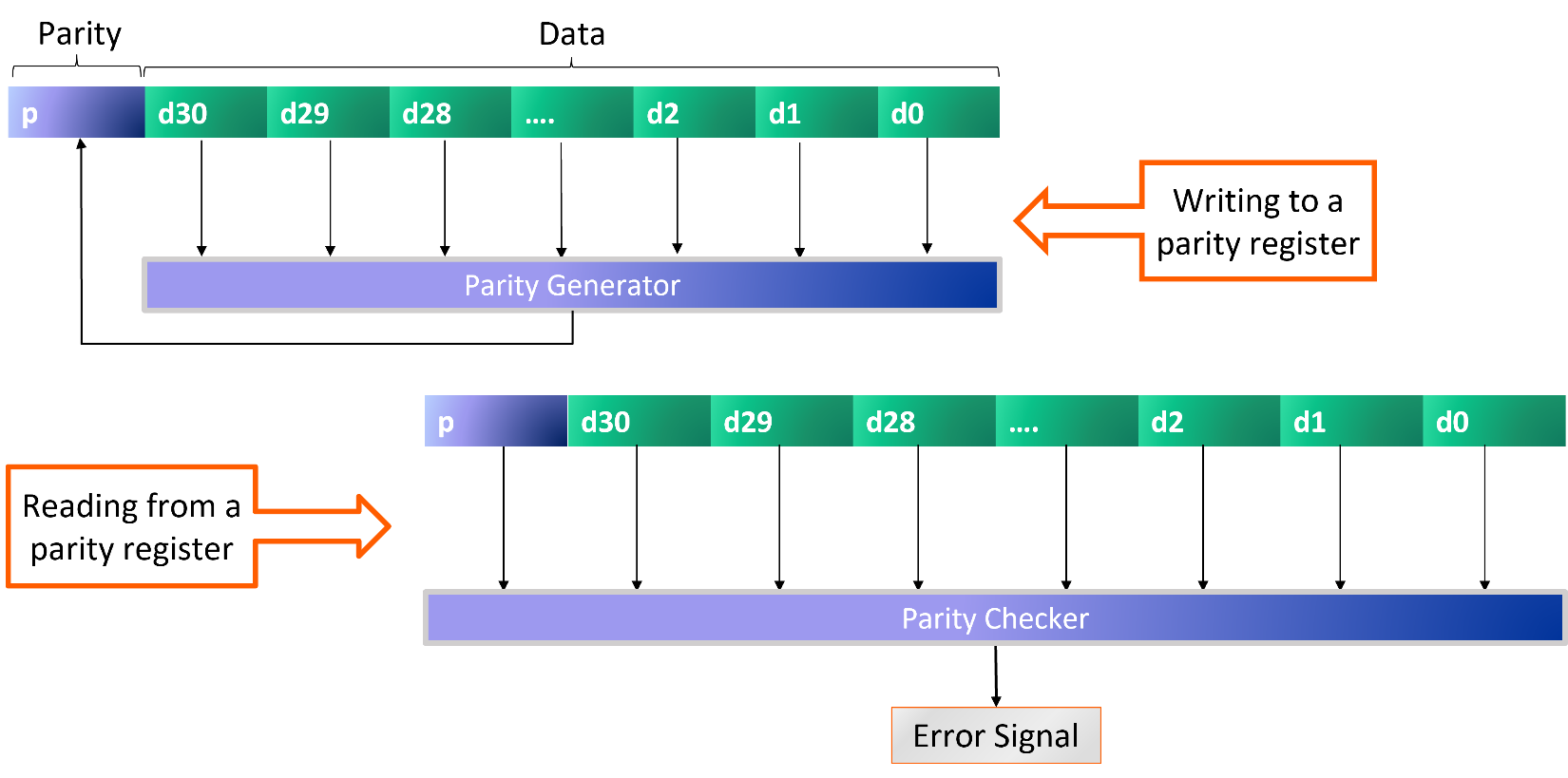
When users define their registers and memories using our IDS NextGen™ (IDS-NG) solution, we offer the option to include parity bits. We support a single parity bit for the entire data string or a separate parity bit for each byte of data. We also offer the option of adding a parity error injection signal, which forces a parity error and can be used to check for proper functional safety operation not just during design verification, but also when the actual chip is in use in the target application. IDS-NG automatically generates the RTL design code for the registers, generators, and checkers as well as the models needed for a Universal Verification Methodology or UVM testbench for the design.
The concept of check bit generation and checking is similar to the cyclic redundancy check (CRC) approach, which can detect additional types of errors. It is especially suited for detecting common failures on communication channels, or on data from communication channels stored in registers or memory. A CRC generator produces a check value based on the remainder of a polynomial division of the data. The checker repeats the calculation and reports an error if the new and old values do not match.
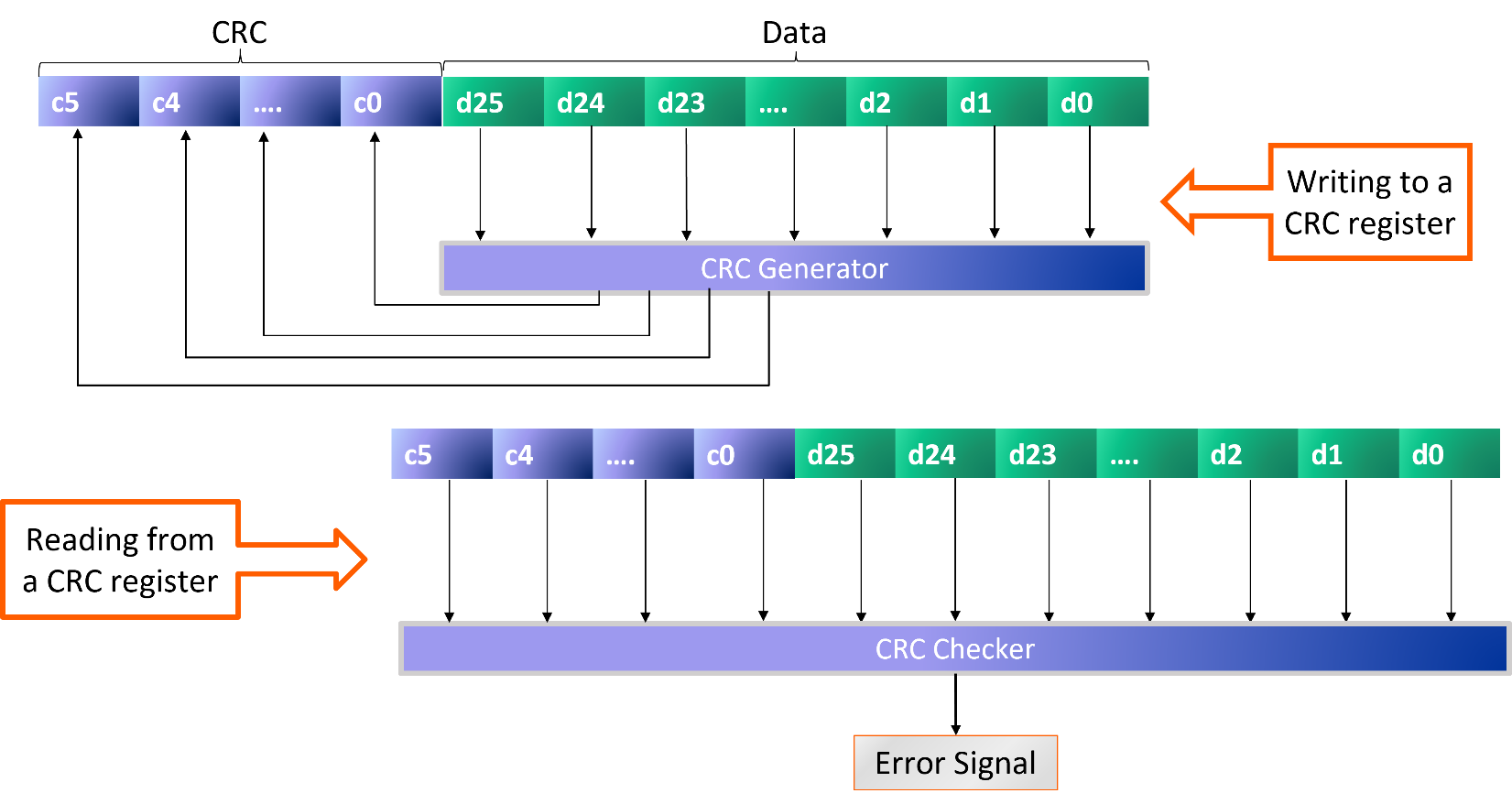
IDS-NG automatically generates all the design and verification codes for CRC-protected registers and memories, with the user option to choose the seed (initial value of the polynomial). We also offer the option to generate a sniffing engine, a hardware mechanism to check the contents of all registers and memories. It walks through the entire address map, reading data values and checking them against the parity or CRC fields. The engine can optionally set an error flag and record the address of a failing register or memory location.
Some types of check bits can correct as well as detect errors. One popular choice is extended Hamming code, which provides single (bit) error correction and double (bit) error detection (SECDED). This level of protection requires extra check bits beyond parity. For example, six extra bits can cover 64 bits of data. IDS-NG automatically generates SECDED generators and decoders, including an option for error injection. Double-bit errors are reported on an error signal; the user can choose whether single-bit errors are corrected silently or also reported.
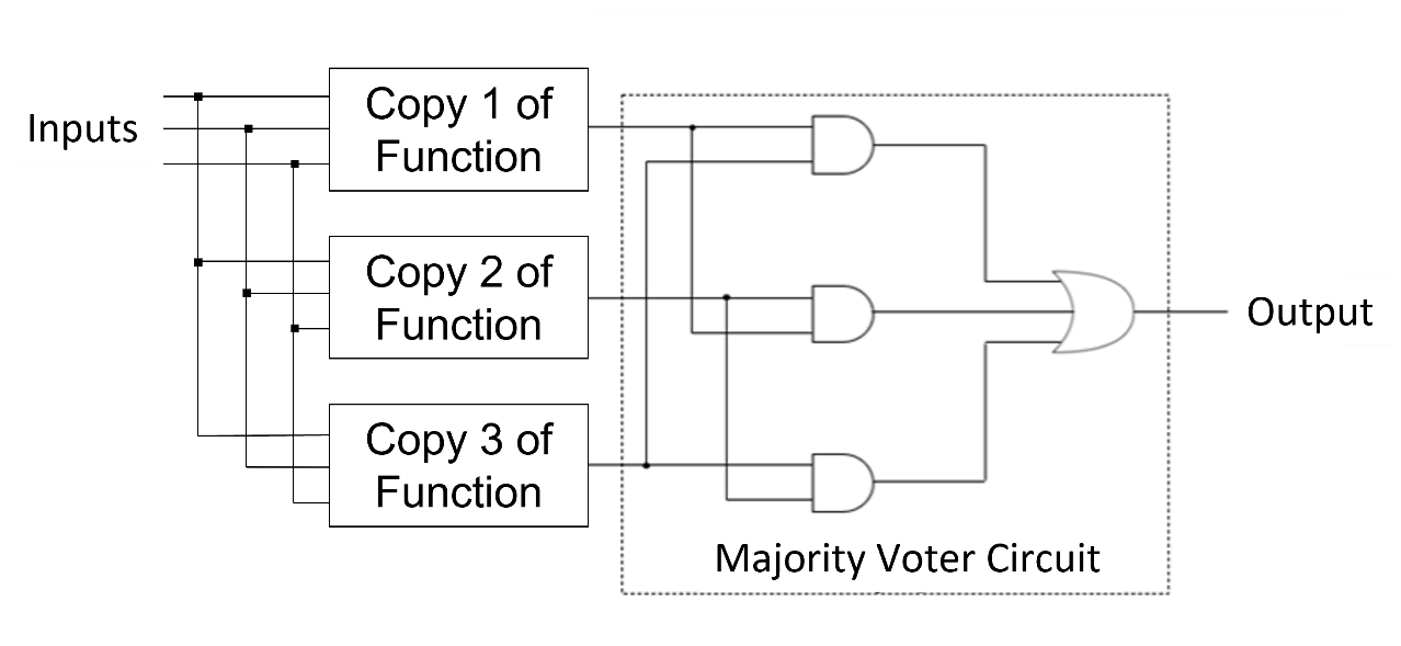
A final example of error detection and correction for functional safety is the long-established method of triple module redundancy (TMR). The concept is straightforward: three identical logic modules perform every safety-critical function in parallel, and a majority voter circuit checks each output. If any of the three modules has an error in its output, the other two modules, providing the correct value, form a majority, and that value is passed on. Checking each output signal has the potential to correct many simultaneous failures. As with the other techniques, IDS-NG automatically generates TMR design and verification code for user-selected functions, including options for error reporting and error injection.
Designing for functional safety is challenging, but it is required for many applications and mandated by many standards. Agnisys does a lot to help, and in this post, I’ve discussed a few of the ways. For more details and additional methods, I highly recommend watching our webinar “IDS-NG for Safety-Critical Designs” here. Together we can ensure that your chips behave properly under duress and provide the necessary protection for the end users.


