Streamlining FPGA Design from Specification to Bitstream
Hardware is verified using simulators. Software compiled and debugged using compilers and debuggers. When it comes to the hardware/software interface, it’s not so straightforward. The FPGA development process can be fragmented in this first phase of design specification.
Take the ARM AMBA® AXI4LITE bus, for example, the most popular bus for inter-chip communication in Xilinx devices. Hardware designs with configuration and status registers addressable by the AXI4LITE register bus are common. Users usually manually create RTL code registers, validate them with the Universal Verification Methodology (UVM), and generate additional firmware artifacts and code fragments.
Certainly, a register generation tool can automate the production of RTL code. However, integrating it with the rest of the application logic and handling specification changes requires manual intervention. The Vivado Design Suite interface addresses the integration process, but generating files is necessary for seamless integration without glitches.
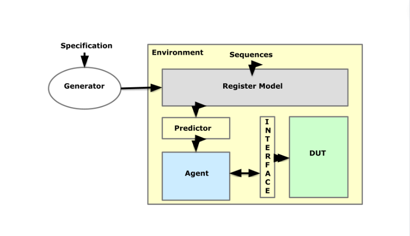
Another promising solution would be to use a correct-by-construction approach. In this scenario, a specification-driven FPGA design flow combining a tool to generate executable design code with Vivado offers a means to create a design specification with information that flows uninterrupted to the bitstream.
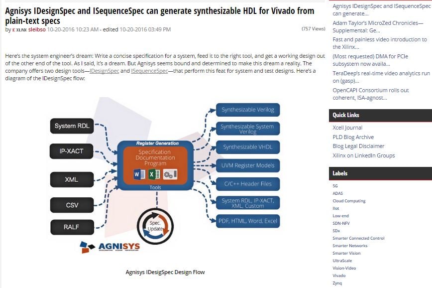
The design specification tool captures the hardware specification to enable an architect or system designer to capture hardware/software specifications in any format, including Word, Excel, SystemRDL, IP-XACT, RALF, or CSV. It generates all possible outputs, such as Verilog, VHDL, SystemVerilog, SystemC, UVM, C headers, SystemRDL, IPXACT, HTML, and datasheets without data re-entry or duplication. You can utilize it to generate a variety of outputs and import various inputs.
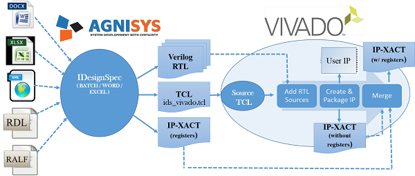
Because information flows from one system to the other, an integrated design flow is devoid of duplicate data entry. The basic linkage is through Verilog files generated by the design specification tool and imported into Vivado. The design specification tool creates IP-XACT with register, pin, and parameter details, while Vivado-generated files have been constructed for seamless operation in Vivado.
To create a register specification in a format for the design specification tool, a user would generate Verilog RTL code and a Vivado TCL application programming interface- (API) supported script. He or she would start the project in Vivado, source the generated script (ids_vivado.tcl) to automatically add sources, compile the design, and create and package the IP with the AXI interface. The packaged IP would go into the user’s IP repository for integration with Xilinx IP, and the generated RTL code could be connected to the rest of the design.
As for the AMBA® AXI4LITE bus example, the design specification tool would generate an RTL code for the AXI client IP for the bus with a configuration setting. The generated client has an AXI bus interface on one end and hardware interface signals on the other, replacing the GPIO block. The tool can produce a TCL script to add the AXI client IP to Vivado.
From there, the user would create a new project in Vivado targeting the Zedboard and a new design in the project where the AXI client IP would be used. The user then would add the AXI client IP to the Viivado IP catalog using the TCL script. The Repository Manager would point the way to the AXI client IP and the added repository would be available from the IP Catalog.
The FPGA development process doesn’t need to be fragmented or a manual effort. The specification-driven flow using IDesignSpec, design specification software from Agnisys, and Vivado is a way to streamline the design specification and the bitstream process.