
Using PSS for Sequence Specification and Generation
Content
Specification automation is an important technology that spans many aspects of intellectual
property (IP) and system-on-chip (SoC) development. From executable specifications, electronic
design automation (EDA) tools automatically generate many diverse types of files used for the
design, verification, programming, validation, and documentation of IP and SoC projects.
This saves enormous engineering effort over the traditional approach of imprecise and
ambiguous natural language specifications followed by hand-coding of all the files required for
the development process.A manual flow also prolongs the project schedule, delaying time to
market (TTM) and compromising the value of the end product. Every time that a specification
changes, the files must be updated manually as well, further increasing project cost and TTM.
Specification automation is applied both for initial file creation and for updates of these files
whenever an executable specification is modified. There are many different file formats both for
input specifications and generated output files that must be supported for a widely applicable
solution. This eBook focuses specifically on the sequences used to program and control the SoC
or IP design and on the specification and generation of these sequences using the Portable
Stimulus Standard (PSS).
Overcoming the weaknesses in the traditional approach requires writing the project design specifications in a precise, executable format. Such a format both eliminates the ambiguity of natural language specifications and enables the automatic generation of many files required by the IP or SoC design, verification, programming, validation, and documentation teams. Specification automation has several benefits for all these teams. Automation is faster than hand coding, so the files are generated more quickly and less expensively.
Any risks of different interpretations of the specifications among the teams and resulting divergent files is eliminated. For example, both the register transfer level (RTL) design and the C/C++ code that programs the design are consistent, avoiding the traditional mismatches found during pre-silicon validation, in the bringup lab, or even during actual use in the field. These benefits are replicated many times over the course of the project. Every time that a specification is updated, it is automatically propagated to all teams and all required files are re-generated in a consistent fashion.
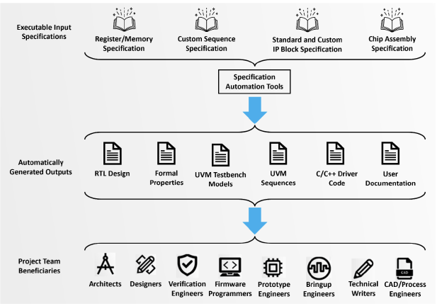
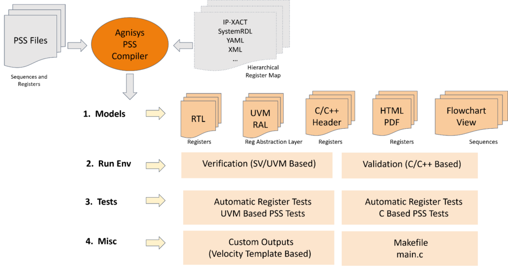
A specification automation solution must read in executable specifications and generate a wide variety of files used by multiple project teams. This process must include support for registers and memory, sequences, standard IP blocks, and chip-level interconnection. Figure 1 provides a concise view of the full range of a complete specification automation solution.
The Role of Registers
There are many types of registers in modern IP and SoC designs. Many of these, such as buffers, queues, delay chains, and pipeline staging points are part of the detailed design along with datapath elements and control structures such as state machines. These registers are usually not visible to programmers or users of the design, and they may vary a lot across different implementations of the same high-level architecture. Registers that are defined as part of the architecture are termed “architecturally visible” since they are included in user manuals and other high-level specifications consulted by both programmers and end users.
The term “control and status registers” (CSRs) is also widely used since these registers control the operation of the hardware design and report back various information on the status of the hardware. For example, performing an arithmetic operation on two values in a processor usually entails choosing two of the general-purpose registers (GPRs), loading the appropriate opcode into the instruction register and initiating the arithmetic operation (control), loading the result into another GPR, and setting status bits that indicate results such as overflow, underflow, or division by zero.
Defining the GPRs and memories is straightforward since they contain numerical values. However, the CSRs can be quite complex. They typically have numerous single-bit and multi-bit fields whose specification and design implementation flow is critical for correct operation of the IP or SoC. Across the full set of architecturally visible registers, there are more than twenty special types that regularly appear in designs. These types include indirect, indexed, read-only/write-only, alias, lock, shadow, FIFO, buffer, interrupt, counter, paged, virtual, external, and read/write pairs. The method of register specification must include the ability to designate these types, cross-combinations of these types, and intermixing of these types (for example, when some bits of a single register are read-only while others are read-write).
The specification automation solution must support numerous ways to specify the registers and memories in a design. These should include standard formats such as SystemRDL and IP-XACT, de facto standards such as Microsoft Word documents and Excel spreadsheets, and an intuitive custom editor. The tools in the solution automatically generate the register-transfer language (RTL) design for the registers, completely freeing the designers from manual coding. The generated code includes asynchronous clock domain crossing (CDC) synchronization logic as needed, interfaces for buses that access the registers (AHB, APB, AXI, AXI-Lite, TileLink, or proprietary), and safety mechanisms required by standards such as ISO 26262 and IEC 61508. All special register types and their combinations are supported. Whenever the register specification changes, the RTL is re-generated automatically, for additional savings in project time and resources.
Complete the form to download
your copy of this eBook.
During production operation, the registers are accessed both by the hardware within the design and by low-level software such as drivers, boot code, embedded programs, and firmware. This access must support both the setting of register values for control and reading of register values to gather status information. The ability of software to access registers is critical for design operation and is the main purpose of the hardware-software interface (HSI). Low-level software can control CSRs and check status through this interface. The architectural specification for the IP or SoC defines an application programming interface (API) through which the software team can use the HSI for register access.
At the heart of the API is a set of sequences that access the registers for control and status purposes. These sequences can be quite complex, with many conditional branches. For example, completion of an arithmetic operation is likely to depend on the values of the status bits at the end of the mathematical calculation. The sequences will also vary for the many different types of special registers. The specification automation solution must generate C/C++ code implementing all necessary sequences. This code can be run in simulation with RTL and processor models for pre-silicon verification and on the actual chip in the bringup lab for post-silicon verification. The generated code can also be incorporated into the low-level software. Just as RTL generation frees the designer from manual design, C/C++ generation greatly reduces the amount of hand-programming.
The requirements for generated sequences go well beyond those needed for production operation of the IP or SoC. The design itself must be verified, first in simulation of the hardware and then in pre-silicon validation running alongside the low-level software. In addition to RTL and C/C++ code, the specification automation solution must generate a complete simulation testbench compliant with the Universal Verification Methodology (UVM) standard. The generated testbench should include UVM bus agents, monitors, drivers, adaptors, predictors, and sequences, as well as the makefile and verification plan. These provide pushbutton design verification of all addressable registers and memories, including all special types.
Thorough verification requires more than production sequences. A complete solution automatically generates sequences for the many types of registers supported, including sequences for register fields, register-level sequences, and positive/negative sequences for special register types. The results of running these sequences in simulation are summarized in a graphical report that includes a verification plan showing the coverage metrics and test status. The built-in register and memory tests in UVM typically provide only about 60% coverage. Specification automation closes this gap by generating sequences that provide 100% coverage of register and memory functionality.
While many types of tests are generated automatically based on the register and memory specifications, there are times when verification engineers or programmers wish to define custom sequences. Writing these by hand is time-consuming and error-prone. Even worse, the process must be duplicated for UVM and C/C++, and the resulting code must be updated manually every time that the specification changes. The specification automation should support the definition of custom sequences in a specialized editor, using a rich language and command feature set that includes loops, branch, wait, calls, switch, and macros. From this specification, the solution automatically generates UVM tests, C/C++ code, and files suitable for use by automatic test equipment (ATE) in manufacturing.
The concept of generating both UVM simulation tests and C/C++ code from an abstract sequence specification is a very powerful one. In the last few years, the semiconductor industry and EDA vendors have developed an interest in a general industry solution. The result was PSS, developed and evolved by the Accellera Systems Initiative standards organization. The first version was released in June 2018, and PSS 2.1 was announced in 2022. Any EDA vendor supporting PSS should be an active member of the Portable Stimulus Working Group and a contributor to the ongoing evolution of the standard.
Users sometimes view PSS as the next step beyond UVM, which was also developed as a standard by Accellera. UVM made it much easier to reuse IP designs between projects without having to rework the entire verification environment (testbench and tests). However, UVM focuses purely on SystemVerilog-based simulation and does not address C/C++ for verification, validation, or production code. UVM also provides minimal support for verification reuse across multiple levels of hierarchy, such as leveraging standalone IP testbenches at the subsystem or full-chip level. Thus, it is hard for an IP developer to provide UVM verification IP useful for the SoC team reusing the design.
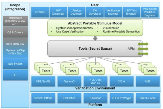
PSS was created to address both these limitations. It enables the specification of verification intent and the automatic generation of tests that work “vertically” from block to system and “horizontally” from simulation to silicon. Figure 2 is a graphical view of this portability developed by Accellera. EDA tools read an abstract PSS model and generate tests for the selected levels of hierarchy and target platform. These tests can be in multiple languages and formats. For example, generated SystemVerilog tests run in UVM testbenches and generated C/C++ tests run in simulation for pre-silicon validation as well as on actual silicon in the bringup lab. These tests also may serve as the basis for production softwar
The capabilities of PSS are quite broad, and many are not relevant to the specification automation space. One key area of overlap is the specification of the architecturally visible registers in an IP or SoC design and the sequences that configure and program these registers. When a design is reset, most of the registers and some types of memories require initialization and configuration to bring the design to a known operational state. Additional programming sequences are required to verify and validate the design before release and to enable production functionality of the chip in the field.
Historically, the relevant sequences had to be specified independently by each team for each hierarchical level and each verification or validation platform. The IP team created standalone SystemVerilog sequences, and these needed to be modified by the chip verification team. Programmers wrote their sequences in C/C++ so that they could run on embedded or host processors. Naturally, there was a high likelihood that these multiple sequences did not match entirely, requiring considerable time and resources to find and fix the inconsistencies during verification and validation. This undesirable process was repeated over and over as the register definitions evolved over the course of the project, with every change introducing new opportunities for divergent and unsynchronized sequences.
The PSS 2.1 release addressed this dilemma by enabling the definition of registers and sequences in an abstract and portable way. EDA tools can then generate the sequences specifically for each level of hierarchy and each platform, ensuring that they are all in agreement. This automated process is repeated every time that the registers change, ensuring that all register programming tests remain in sync. Each IP team specifies its registers and sequences, and engineers working at higher levels of the design hierarchy can simply generate appropriate tests without having to know details or change the specifications. Clearly, this yields enormous savings in project time and cost.
A complete specification verification solution is positioned perfectly to leverage the advantages of PSS in two valuable ways. First, it can generate both register models and programming sequences in PSS code. This makes it easy to fit into projects that have a PSS-based verification and validation flow, and to merge register sequences with other tests generated by a PSS tool. In addition, engineers on projects that have chosen PSS as their primary specification for verification intent may want to use the language for specifying their registers and sequences. Users can specify everything using the portable stimulus format and automatically generate both SystemVerilog/UVM and C/C++ tests. The solution should include a PSS editor to help users write their models. If the project has a mix of register and sequence definitions in PSS and other formats, the solution must be able to merge them together in the generated output tests.
The Agnisys Solution
Agnisys is the undisputed industry leader in specification automation. For more than fifteen years, the Agnisys IDesignSpec™ Suite has read in executable golden specifications and automatically generated a wide variety of files for design, verification, programming, validation, and documentation. These include all the formats mentioned so far. The company started with support for registers and memory, and over the years added support for sequences, standard IP blocks, and chip-level interconnection.
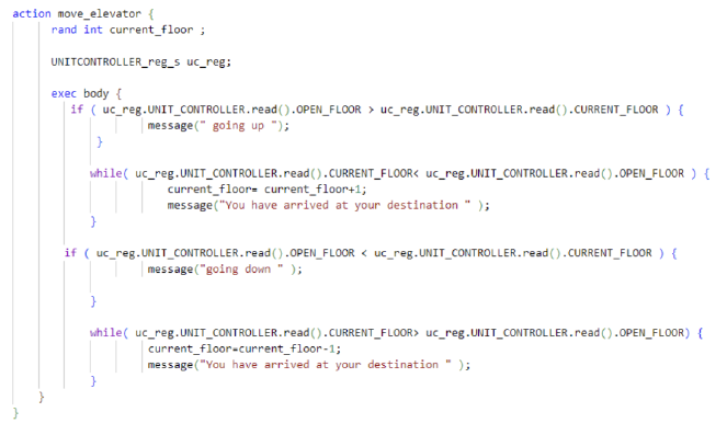
The IDesignSpec Suite leverages the advantages of PSS in both ways previously listed as requirements for a complete portable stimulus solution. The solution has many options for register and sequence specification, and the ability to directly generate SystemVerilog and C/C++ tests for specific platforms. The capability to generate both register models and programming sequences in PSS code is now available. Figure 3 shows an example of automatically generated
PSS code.
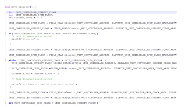
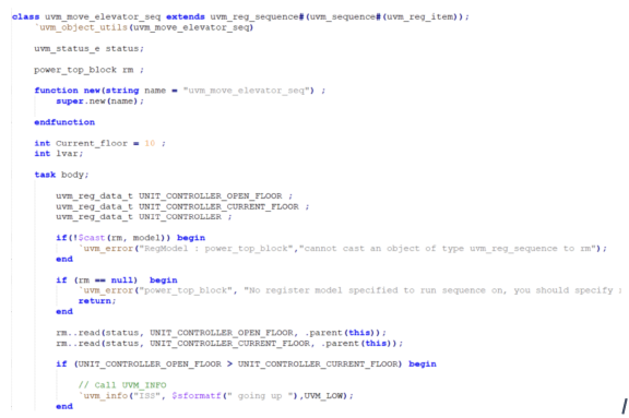
The IDesignSpec Suite now also supports using PSS for register, memory, and sequence specification. It includes an intuitive and intelligent PSS editor built on the widely adopted Visual Studio (VS) Code platform . Users can automatically generate both SystemVerilog/UVM and C/C++ tests from PSS models and merge these with tests generated from other input formats. Figure 4 and Figure 5 show examples of C/C++ and SystemVerilog/UVM test code automatically generated from PSS models.
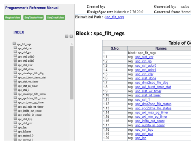
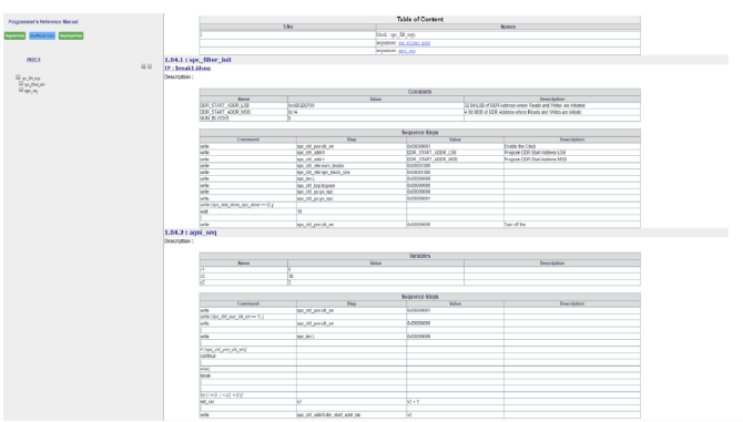
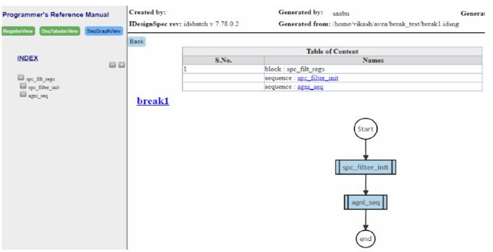
The IDesignSpec Suite also generates a Programmer’s Reference Manual (PRM) that serves as a comprehensive documentation resource for programming sequences and hardware architecture. It is a key reference for programmers, developers, and end users seeking a detailed understanding of the intricacies of the IP or SoC design. The PRM comprises three beneficial views:
- The Register View provides complete information on register and memory data.
- The Sequences Tabular View presents detailed information about sequences in a tabular format. Users can conveniently track and access information related to each sequence.
- The Flowchart View includes a graphical representation or flowchart illustrating the sequences, offering a visual understanding of the information flow.
Users can generate the PRM interactively from within IDesignSpec GDI or via a command line using IDS-Batch CLI. Figure 6, Figure 7, and Figure 8 provide examples of all three views.
Support for portable stimulus has been integrated into many aspects of the Agnisys solution, enabling it to automatically generate many different types of files from registers and sequences specified in the PSS format. Figure 9 summarizes these generation capabilities.
There is some overlap in the capabilities of the IDesignSpec Suite and PSS tools, in that both can accept PSS specifications and generate C/C++ and UVM tests for registers and sequences. The IDesignSpec Suite also generates RTL designs, SystemVerilog Assertions (SVA), and high-quality documentation for registers in addition to sequences. It also provides specification automation for standard IP blocks, state machines and other components within custom IP blocks, automated connection of IP blocks within an SoC, and more. With the PSS support provided by Agnisys, these two solutions interact seamlessly.
Manual specification of designs and sequences was expensive, time-consuming, and error-prone. This is not just a one-time cost; RTL, UVM, C/C++, and documentation files had to be updated by hand every time that the specification changed. Specification automation is a much better solution that pays dividends to all project teams throughout any IP or SoC project. Users can write specifications in executable golden formats and generate many types of files automatically. Since PSS is an important emerging way to specify verification intent in an abstract way, Agnisys has added support for portable stimulus in the IDesignSpec Suite alongside the many other formats read and generated. This allows users to interact with PSS solutions from other vendors and to leverage this state-of-the-art standard. To learn more, visit www.agnisys.com.
Complete the form to download
your copy of this eBook.


